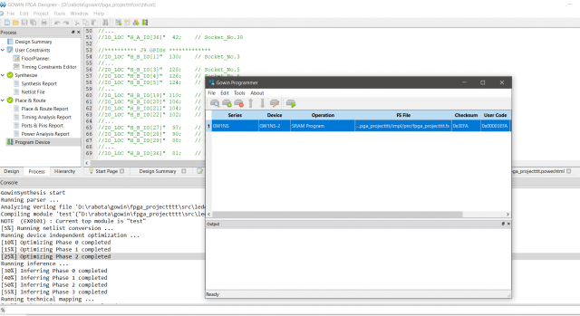
При запуске программы плата не делает, что должна
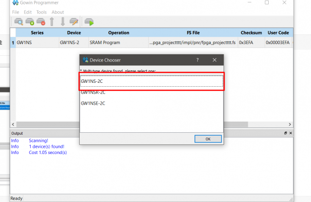
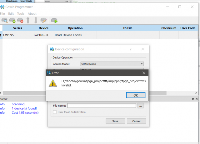
Создается проект -> создается файл Verilog -> туда пишется код для мигания лампочки (код ниже) -> Нажимается "Place & Route -> Return All" -> Далее в программере выбирается подключенная плата, режим SRAM Program, где указывается файл с кодом. После запуска плата приходит в состояние как на фото и ничего больше не происходит.
Плата GW1NS-UX2CLQ144C5/I4
module demo ( // Declare our demo module.
clk_50M, // Declare 3 pins: clk_50M, rst_n, led.
rst_n, // We will connect these pins to the
led); // actual clock signal, reset signal and LEDs.
input clk_50M; // Declare the clock pin as an Input signal.
input rst_n; // Reset pin is also an Input, triggered by board restart or reset button.
output[3:0] led; // LED is actually 4 discrete LEDs at 4 Output signals. Each LED Output is 1 bit.
// So think of "output[3:0] led" as an Output array of 4 bits: "output led[0], led[1], led[2], led[3]"
reg[3:0] led; // Declare led (4 bits), cnt (25 bits) and clk_led (1 bit) as Registers that
reg[24:0] cnt; // can remember a value in volatile FPGA memory (similar to RAM).
reg clk_led; // So led refers to a 4-bit Output signal that is remembered when it gets updated.
// This block increments a counter and flips the clk_led bit on or off upon overflow.
always@( // Code below is always triggered when these conditions are true...
posedge clk_50M or // When the clock signal transitions from low to high (positive edge) OR
negedge rst_n // When the reset signal transitions from high to low (negative edge) which
) begin // happens when the board restarts or reset button is pressed.
if (!rst_n) begin // If board restarts or reset button is pressed...
clk_led <= 1'b0; // Init clk_led and cnt to 0. "1'b0" means "1-Bit, Binary Value 0"
cnt <= 25'd0; // "25'd0" means "25-bit, Decimal Value 0"
end
else begin
if (cnt == 25'd2499_9999) begin // If our counter has reached its limit...
clk_led <= ~clk_led; // Toggle the clk_led from 0 to 1 (and 1 to 0).
cnt <= 25'd0; // Reset the counter to 0.
end
else begin
cnt <= cnt + 25'd1; // Else increment counter by 1. "25'd1" means "25-bit, Decimal Value 1"
end
end
end
always@( // Code below is always triggered when these conditions are true...
posedge clk_led or // When the clk_led register transitions from low to high (positive edge) OR
negedge rst_n // When the reset signal transitions from high to low (negative edge) which
) begin // happens when the board restarts or reset button is pressed.
if (!rst_n) begin // If board restarts or reset button is pressed...
led <= 4'h1; // Init the 4-bit led value to 1. "4'h1" means "4-bit, Hexadecimal Value 1".
end // Value 1 means ON, ON, ON, OFF for the 4 LEDs (see above)
else begin
led <= { led[2:0], led[3] }; // Else we shift the LEDs left 1 place (see above)
end
end
endmodule