Как подключить xds100v2 к tms320vc5509a выдает ошибку
Error connecting to the target:
(Error -1063 @ 0x0)
Device ID is not recognized or is not supported by driver. Confirm device and emulator configuration is correct, or update device driver.
(Emulation package 5.0.569.0)
CCS 5.1 обновлял. windows 7 32bit
Дрова xds100v2 установленны правельно.
При тестировании в 5.1.1.00031 xds100v2 выдает
[Result]
-----[Print the reset-command software log-file]-----------------------------
This utility has selected a 100- or 510-class product.
This utility will load the adapter 'jioserdesusb.dll'.
The library build date was 'Dec 19 2011'.
The library build time was '21:32:12'.
The library package version is '5.0.569.0'.
The library component version is '35.34.39.0'.
The controller does not use a programmable FPGA.
The controller has a version number of '4' (0x00000004).
The controller has an insertion length of '0' (0x00000000).
This utility will now attempt to reset the controller.
This utility has successfully reset the controller.
-----[Print the reset-command hardware log-file]-----------------------------
The scan-path will be reset by toggling the JTAG TRST signal.
The controller is the FTDI FT2232 with USB interface.
The link from controller to target is direct (without cable).
The software is configured for FTDI FT2232 features.
The controller cannot monitor the value on the EMU[0] pin.
The controller cannot monitor the value on the EMU[1] pin.
The controller cannot control the timing on output pins.
The controller cannot control the timing on input pins.
The scan-path link-delay has been set to exactly '0' (0x0000).
-----[The log-file for the JTAG TCLK output generated from the PLL]----------
There is no hardware for programming the JTAG TCLK frequency.
-----[Measure the source and frequency of the final JTAG TCLKR input]--------
There is no hardware for measuring the JTAG TCLK frequency.
-----[Perform the standard path-length test on the JTAG IR and DR]-----------
This path-length test uses blocks of 512 32-bit words.
The test for the JTAG IR instruction path-length succeeded.
The JTAG IR instruction path-length is 38 bits.
The test for the JTAG DR bypass path-length succeeded.
The JTAG DR bypass path-length is 1 bits.
-----[Perform the Integrity scan-test on the JTAG IR]------------------------
This test will use blocks of 512 32-bit words.
This test will be applied just once.
Do a test using 0xFFFFFFFF.
Scan tests: 1, skipped: 0, failed: 0
Do a test using 0x00000000.
Scan tests: 2, skipped: 0, failed: 0
Do a test using 0xFE03E0E2.
Test 3 Word 3: scanned out 0xFE03E0E2 and scanned in 0x7F01E0E2.
Test 3 Word 4: scanned out 0xFE03E0E2 and scanned in 0x7F00F831.
Test 3 Word 5: scanned out 0xFE03E0E2 and scanned in 0xFE03E071.
Test 3 Word 7: scanned out 0xFE03E0E2 and scanned in 0x7F01E0E2.
Test 3 Word 8: scanned out 0xFE03E0E2 and scanned in 0xFE01F071.
Test 3 Word 9: scanned out 0xFE03E0E2 and scanned in 0x7F01E0E2.
Test 3 Word 10: scanned out 0xFE03E0E2 and scanned in 0xFE01F071.
Test 3 Word 11: scanned out 0xFE03E0E2 and scanned in 0x7F01F062.
The details of the first 8 errors have been provided.
The utility will now report only the count of failed tests.
Scan tests: 3, skipped: 0, failed: 1
Do a test using 0x01FC1F1D.
Scan tests: 4, skipped: 0, failed: 2
Do a test using 0x5533CCAA.
Scan tests: 5, skipped: 0, failed: 3
Do a test using 0xAACC3355.
Scan tests: 6, skipped: 0, failed: 4
Some of the values were corrupted - 51.0 percent.
The JTAG IR Integrity scan-test has failed.
-----[Perform the Integrity scan-test on the JTAG DR]------------------------
This test will use blocks of 512 32-bit words.
This test will be applied just once.
Do a test using 0xFFFFFFFF.
Scan tests: 1, skipped: 0, failed: 0
Do a test using 0x00000000.
Scan tests: 2, skipped: 0, failed: 0
Do a test using 0xFE03E0E2.
Test 3 Word 1: scanned out 0xFE03E0E2 and scanned in 0xFE03E0E0.
Test 3 Word 2: scanned out 0xFE03E0E2 and scanned in 0xFE03E0E0.
Test 3 Word 8: scanned out 0xFE03E0E2 and scanned in 0xFE03E0E0.
Test 3 Word 10: scanned out 0xFE03E0E2 and scanned in 0xFE03E0E0.
Test 3 Word 16: scanned out 0xFE03E0E2 and scanned in 0xFE03E0E0.
Test 3 Word 18: scanned out 0xFE03E0E2 and scanned in 0xFE03E0E0.
Test 3 Word 25: scanned out 0xFE03E0E2 and scanned in 0xFE03E0E0.
Test 3 Word 31: scanned out 0xFE03E0E2 and scanned in 0xFE03E0E0.
The details of the first 8 errors have been provided.
The utility will now report only the count of failed tests.
Scan tests: 3, skipped: 0, failed: 1
Do a test using 0x01FC1F1D.
Scan tests: 4, skipped: 0, failed: 2
Do a test using 0x5533CCAA.
Scan tests: 5, skipped: 0, failed: 3
Do a test using 0xAACC3355.
Scan tests: 6, skipped: 0, failed: 4
Some of the values were corrupted - 37.6 percent.
The JTAG DR Integrity scan-test has failed.
[End]
С JTAG кабелем все впорядке
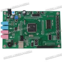
Вот сама плата
DSP5509A
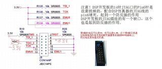
и схема
схема
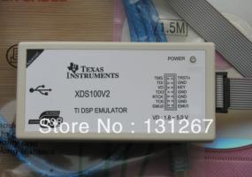
Вот xds100v2 схемы нет
xds100v2
xds100v2 разьем jtag (напряжения на штырях) на схеме одно когда измерял другое. напряжения jtag
Я думаю это ошибку вызывает эмулятор xds100. Как ее исправить уже 2 неделю бьюсь и все 0. Нехочется новый программатор куплять. Помогите
DSP5509__23398___20064___26495___21407___29702___22270_.pdf